HERE ARE SOME PICTURES AND DIRECTIONS TO HELP YOU REBUILD YOUR HAMMOND ORGAN VIBRATO SCANNER.
PLEASE READ ALL OF THE DIRECTIONS BEFORE STARTING !
Rebuild Information Provided By: Brian Walinski (AVintageSound.com)
I will start with saying a few things first. The most common thing to go wrong with your Hammond vibrato (motorboating or chopping sound) is the scanner, There have been a few times that I rebuilt the scanner and it was not the problem but this has happened only a few times. My point is that yes you should try to know for sure that the problem is in the scanner but I have hardly seen a scanner that did not need rebuilt even though it was not the problem (at least for that day). Most of the time they are oil soaked and have a white crystal buildup that will short it out sooner than later. A few things that can be wrong instead of the scanner are the wires going to the scanner are not connected or connected wrong, the white vibrato switches or the switch matrix that the round selector knob controls could have broken wires or that white crystal buildup has shorted out the signal. (an air compressor is handy for this area) There can also be a problem with one of the tubes or the delay line, and so on. There is a lot of information on the net about this, but I cannot find adequate direction with pictures on how to rebuild a scanner, which is usually the problem. If you are unsure of the problem or know that the scanner is the problem, you should rebuild it. There are usually no parts to replace so you will only be out a little time and a few dollars for the cleaner. If the problem is still there, then you can cancel the scanner out.
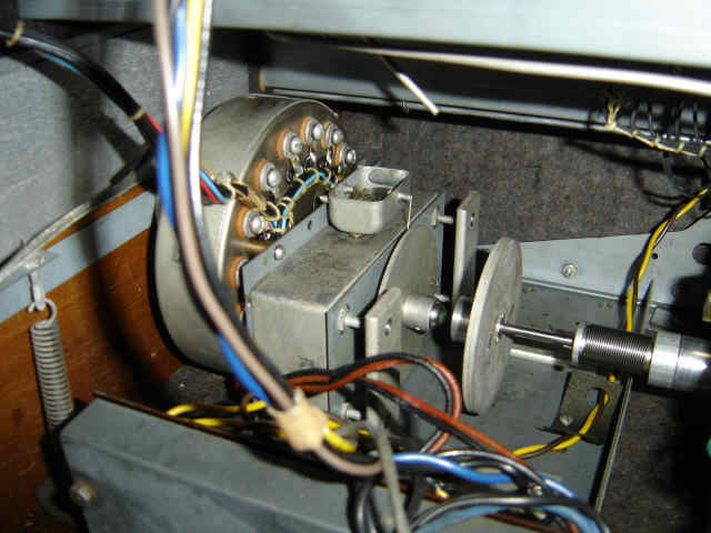
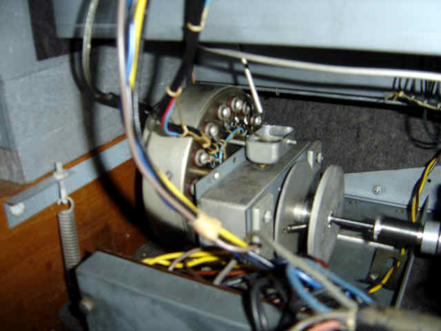
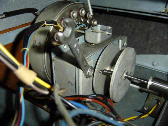
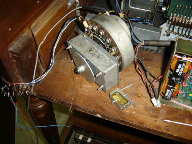
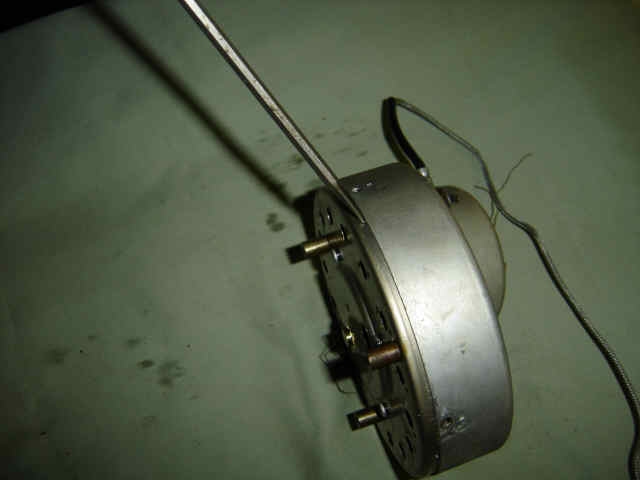
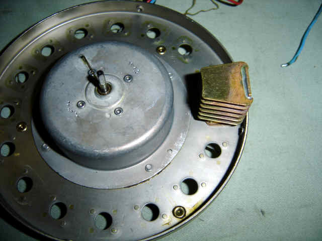
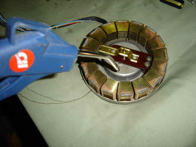
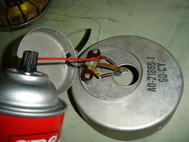
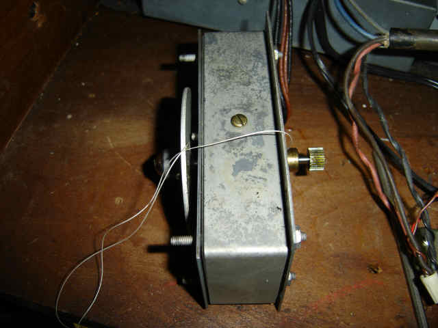
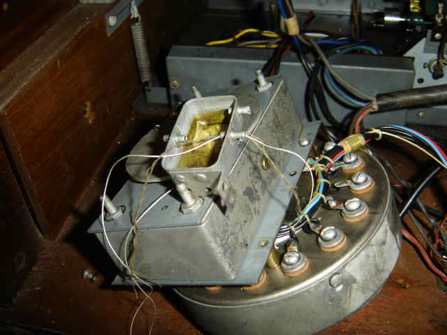
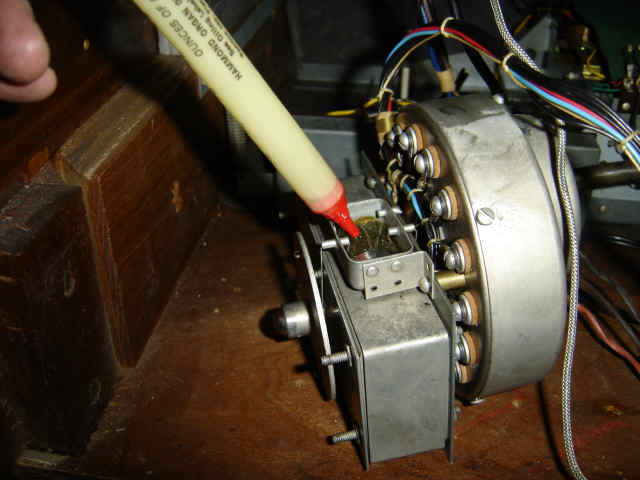
First thing to do is locate the vibrato scanner, it is that round thing with wires connected to that rectangle thing which is the run motor.
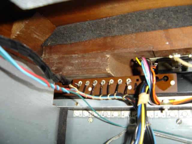
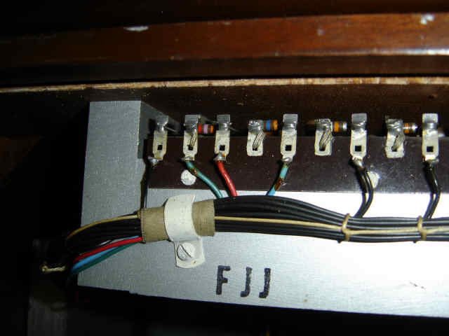
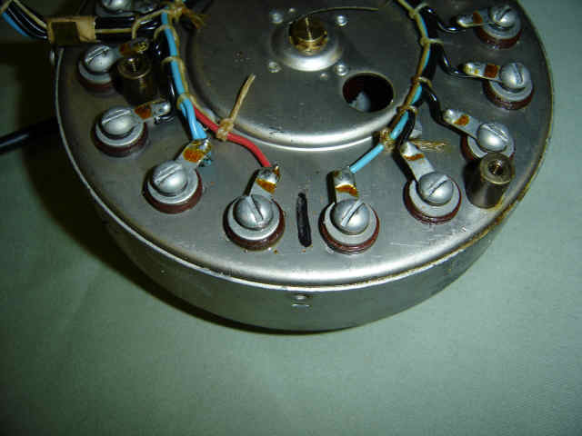
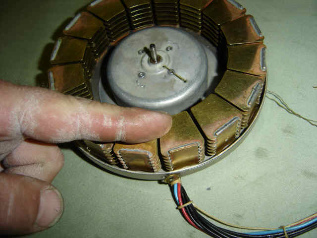
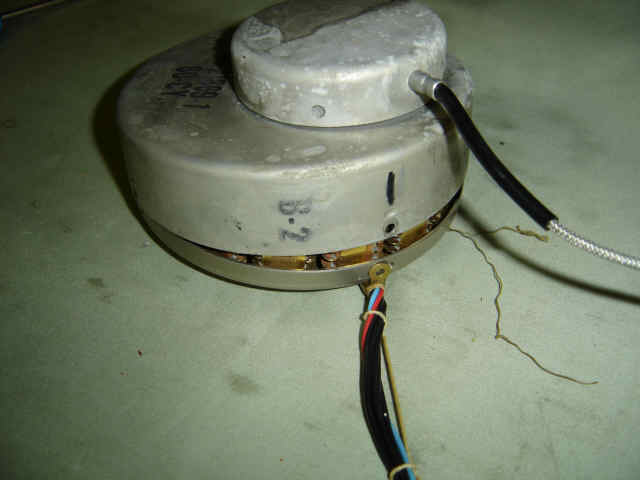
Follow the wires up from the scanner to the vibrato delay line and switch harness and disconnect them. Make sure to note which wire went where, If you reconnect them wrong, it will not work right. Also note the wires are going from right to left and the wires are spaced with the waxy thread or string.
The blue and red wires from the scanner go to the delay line. Some model organs only have a red wire and not a blue wire. Note where the wires were and remove them. (your delay line may not look like this one, there are a few different models)
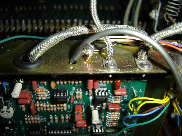
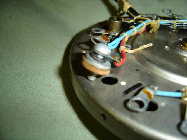
Follow the shielded wire (from the scanner) to the amplifier, it will attach with a screw to the frame, you will also need to remove the cover to the amplifier and unsolder or unscrew the wire. The picture below is where the wire attaches to a Trek II solid state amplifier. Some people disconnect this wire at the scanner, I choose to disconnect it from the amplifier because there is less risk of breaking a fragile pin inside the scanner which you will see soon. Also on older organs, this wire looks a little different and connects to a round thing with a cap on the amplifier (round thing is a very technical name for a part), you will need to remove the cap, then remove the tube, then you can loosen the frame screw and disconnect the wire on the inside of the round thing.
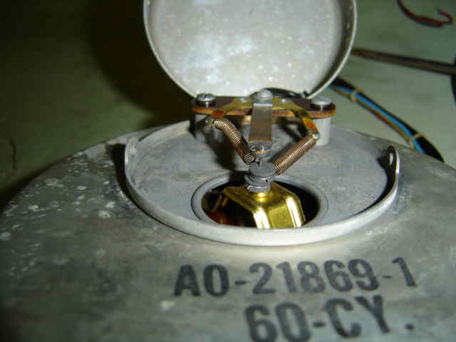
Remove the two springs that hold those two wheels together, these are fun!
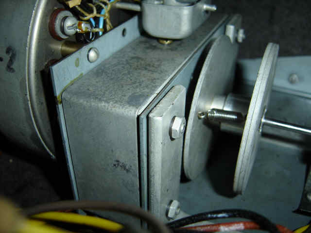
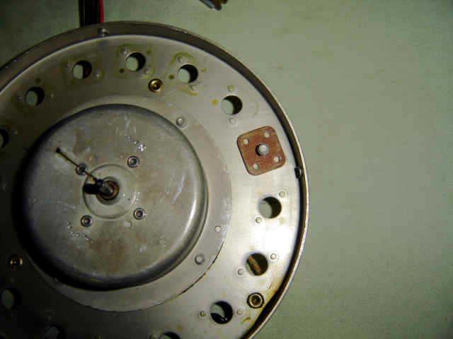
Remove the four 5/16" nuts that hold the run motor to the generator frame. (oops, pretend I already removed those springs)
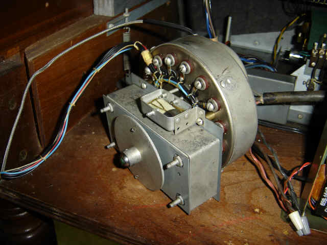
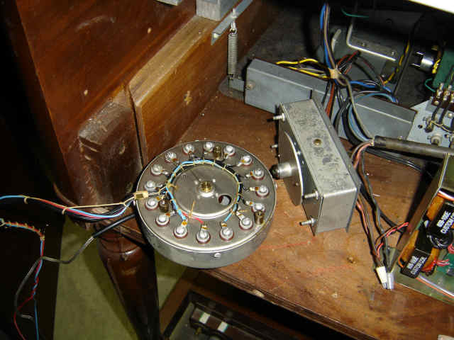
Remove both the run motor and scanner from the generator so we can disconnect them from each other. (When working on an older organ, you will need to remove the amplifier and tray that the amplifier is attached to go get more room or will need to go through the front of the organ. The older organs are a little harder to work on and take a little more time.
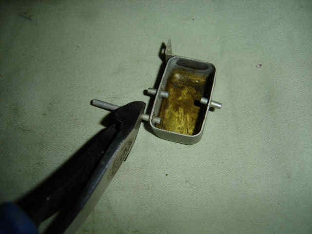
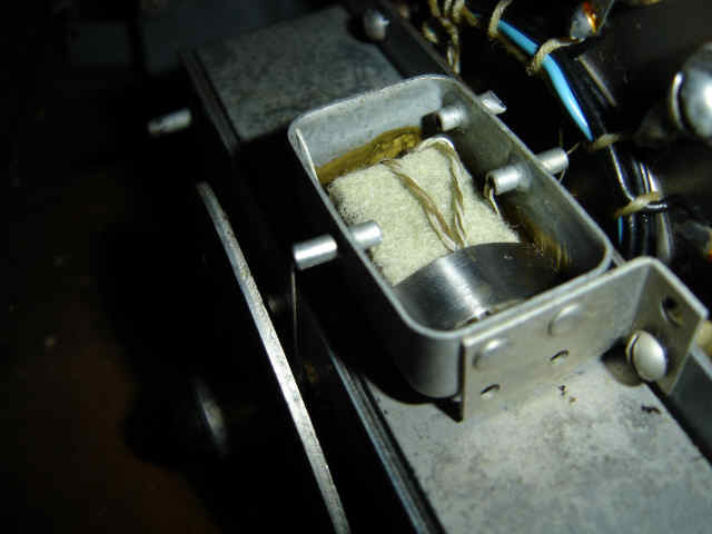
Remove the metal clip that holds the sponge in place, then untangle the threads around the sponge and seperate them, be carefull not to break them. Next remove the screw that holds the sponge tray to the scanner and run motor.
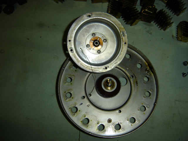
Remove the last two remaining screws and seperate the scanner from the run motor. There is one left on the top and one at the bottom.
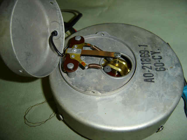
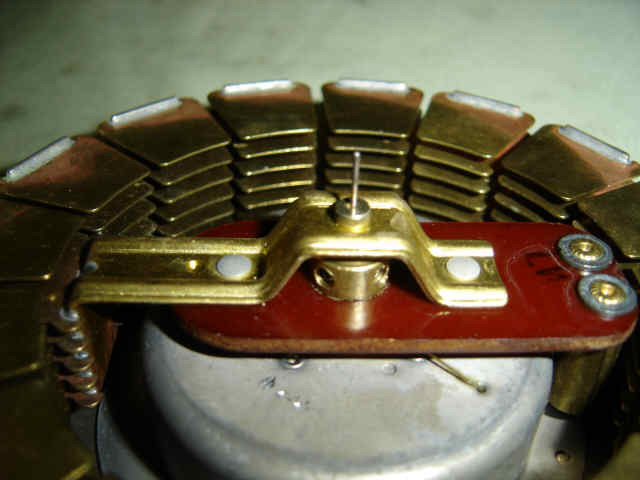
Unscrew the small round cover and remove the contacts from the pin. This is the very fragile pin that I talked about earlier. If you are not carefull and break this pin, we can say you are done and do not need to go on from here.
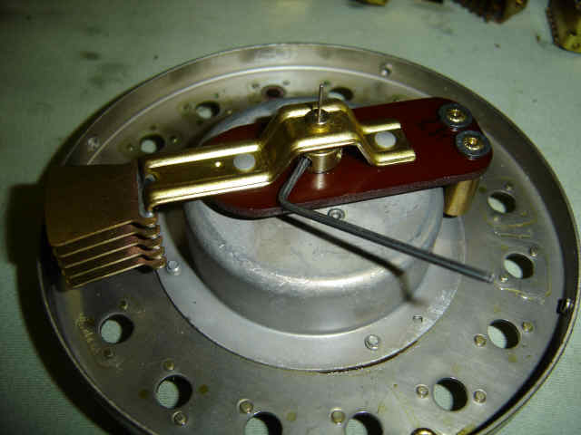
Mark the position of the wire harness which will be needed to put it back together. I used marker for the picture but you should scratch it with a screw driver or something because when you clean the metal, the marker will be washed off.
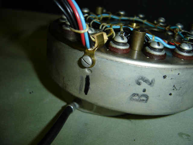
Now mark the position of the wire harness where the wires do not meet. Again scratch the metal, do not use marker.
Loosen all of the screws around the entire wire harness.
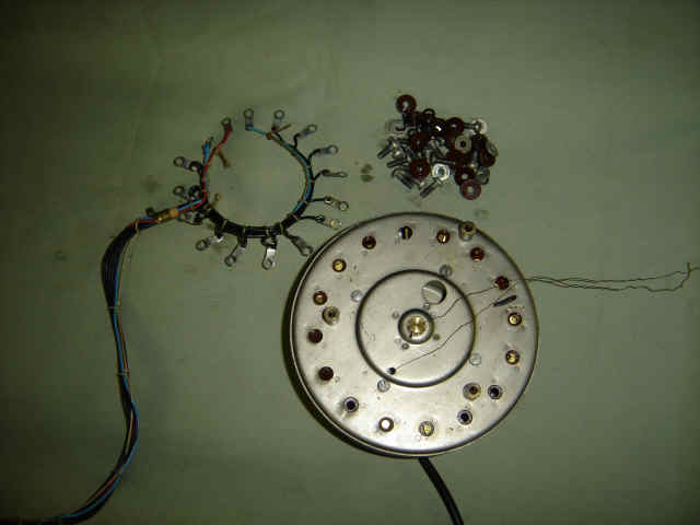
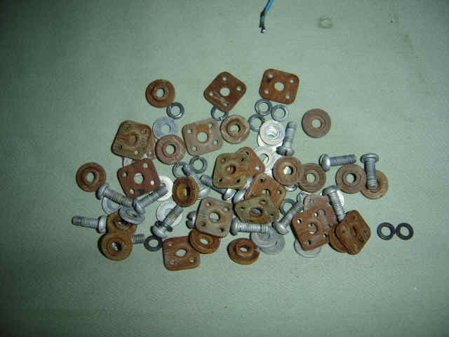
Remove the wire harness, screws, washers, and spacers and put them into a pile.
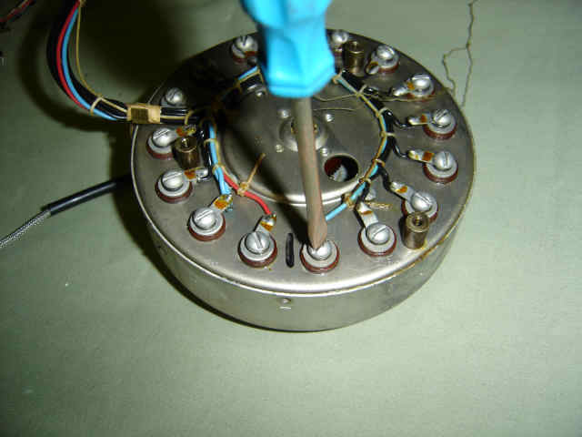
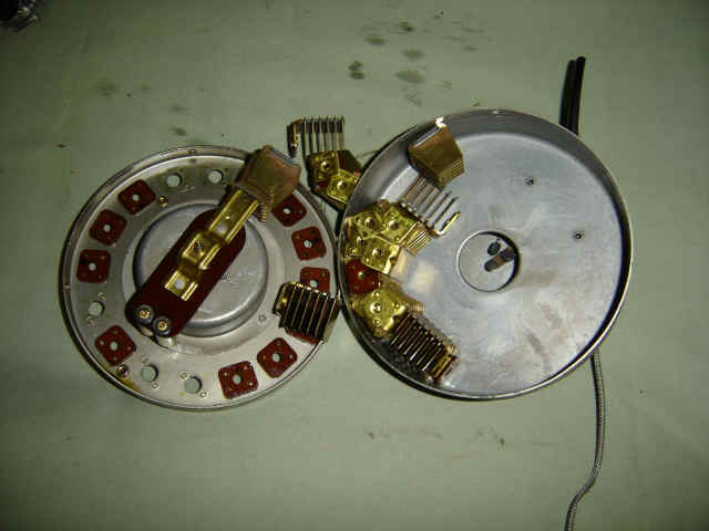
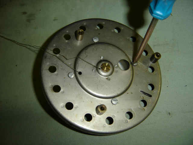
Now we need to separate the front and back pieces, most of the time it will slip apart, but if it will not the next two pictures show how to separate it with a screw driver. Only do this if it is absolutely needed. Put the screw driver NEXT to the piece that spins, be sure you are not on it, tap very lightly, if you tap two hard it will damage the metal and the spindle will not spin. Switch from one side of the spindle to the other. Please look at the next picture before you go too far.
Spread the two pieces by prying them apart, becareful not to damage the threads for the screws. Take you time!
Again, be carefull of the fragile pin and the oil threads
Don't break that pin, (did I jinx you yet)
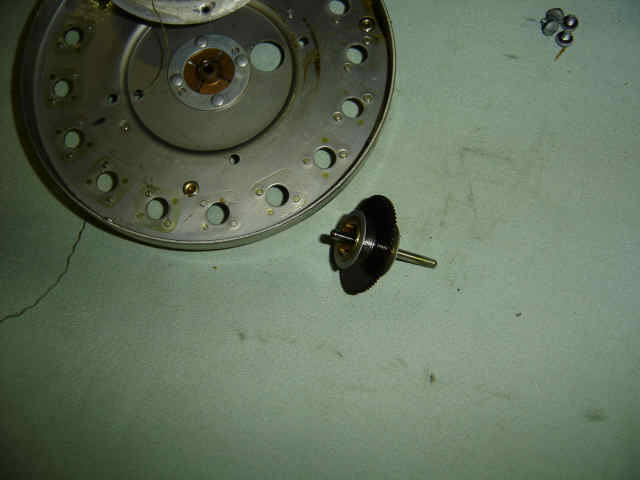
Remove the rotor assembly by loosening the two set screws with a bristol wrench. If you do not have a bristol wrench, you can rebuild the scanner without removing the spindle but it is a lot harder and riskier of breaking the pin.
The next few steps are only needed if the scanner is frozen in place because of a lack of oil. If the spindle spins freely, you should not need to do this. Remove the four screws on the side that the threads come out.
Remove the cover on the back side, watch out for some small washers that are used as shims where the screws come through, they will need to be put back in the same place. Becarefull not to break the thread.
Remove the gear and clean the bushings and gear ends.
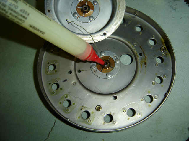
Oil the bushings and make sure the clutch (spring) is not frozen.
Put the cover back on with the washers or shims, make sure the gear spins freely. (All parts will be cleaned with electronic contact cleaner.)
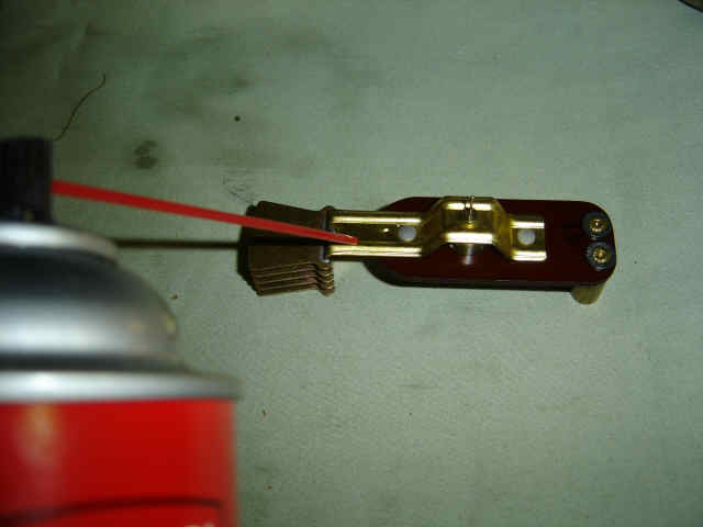
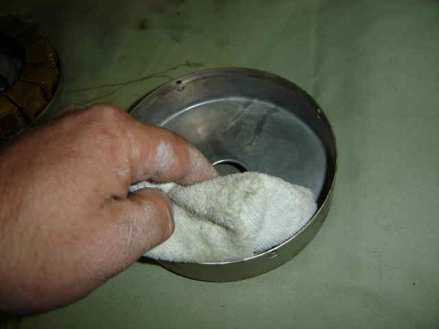
Clean the housing with a clean cloth and some electronic contact cleaner or alcohol. DO NOT USE STEEL WOOL, ONE LITTLE PIECE LEFT OVER CAN SHORT THE SCANNER OUT AND YOU WILL HAVE TO START ALL OVER!
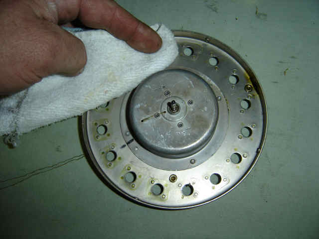
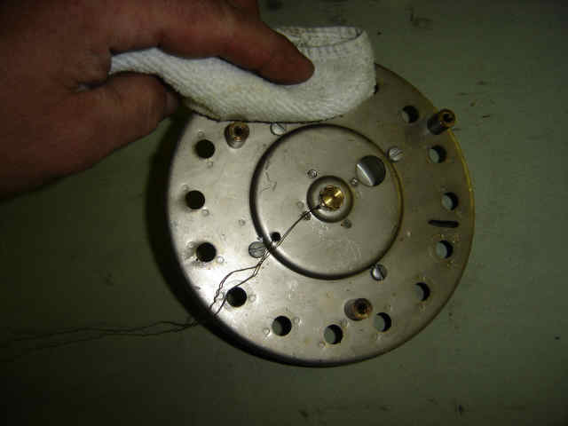
Make sure you clean both sides very well, get all the oil and crystals off. Watch out for the threads
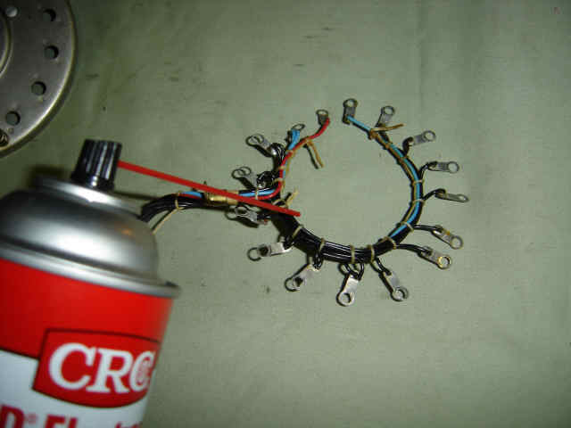
Clean the wire harness.
Clean all of the screws, washers and insulators. It will take a few washes to get all the oil off. I have heard of a few procedures of how to clean all of these parts, I say just get them clean.
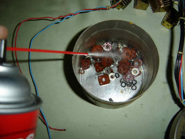
The insulators should have a white color after cleaning.
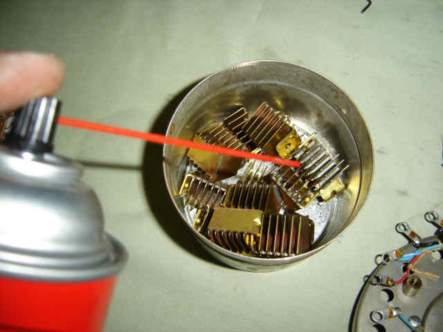
Clean the stationary plates.
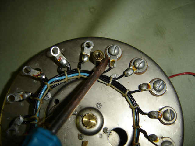
Now that all of the parts are clean we can start putting the scanner back together. Start where you have marked the wire harness. I start with the hole on the right of the line if the line is held at 12:00 noon, and then work counter clockwise.(I am right handed) Screw, wire, lock washer, flat washer, insulator.
After putting the screw through the hole, put the inner insulator on, make sure you line it up in the correct position.
Screw the stationary plate into place, I twist it back and forth a little to make sure it is seated all the way down. Put all of them in except for the last one.
Make sure the wire harness does not short to any metal
Again, make sure the wire harness does not short to any metal.
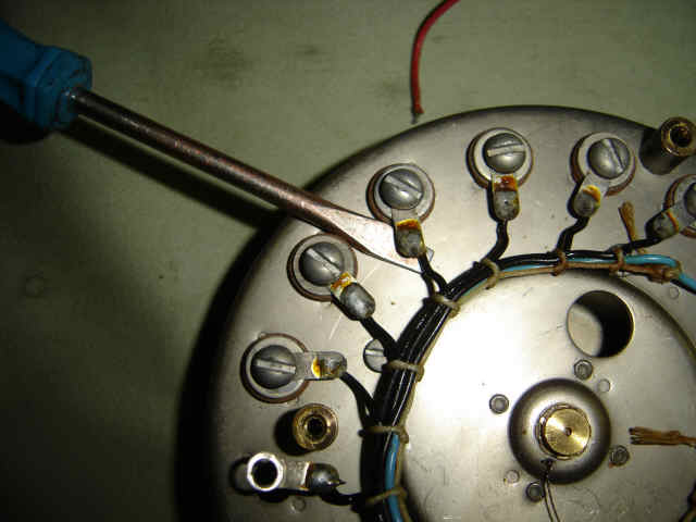
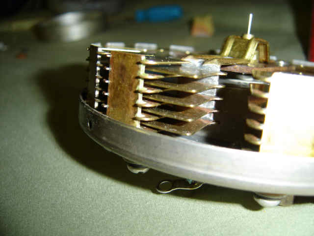
Make sure all of the plates are flush to each other on the top, this will let you know if one is not seated all the way down.
Clean the rotor assembly
Slide the rotor assembly onto the gear shaft. Becarefull, it only goes on one way, the screws should hit the flat spots.

Tighten the two set screws with the rotor plates in the center of the stationary plates. Now you can install the last stationary plate you left out.
Use an air compressor to clean off any dust or crystals that you may have missed, Watch out for the threads again, the air will break them and DO NOT SPIN THE ROTOR WITH THE AIR, IT WILL DAMAGE IT.
Clean the inside of the cover.
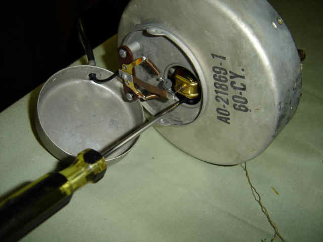
Clean the pin contacts and surrounding area.
Line up your marks where the wire harness was attached to the housing and cover and snap together. Install all four screws that hold it together.
Reinstall the pin contacts and make sure the rotor spins freely. Put the cover back on with both screws.
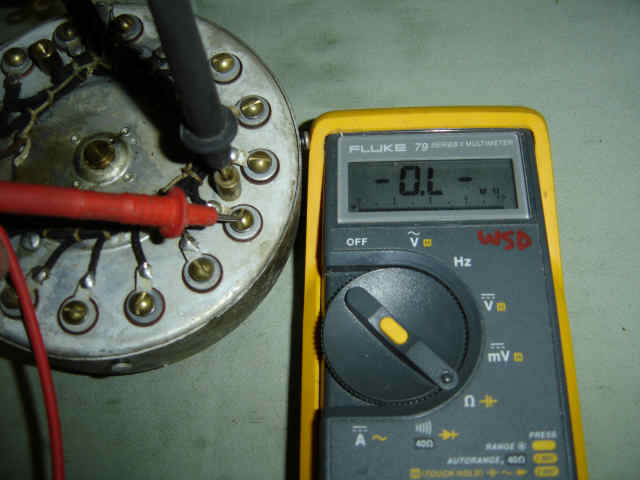
Check each screw attached to the wire harness with an ohm meter, it should be open (no reading at all). If you do have a reading, then something is wrong and it is shorting to ground.
Carefully pull the threads up and out of the way on the scanner and run motor. Reattach the scanner to the run motor with the two screws that did not hold the oil cup.
If your oil cup has this third thread hole, cut it off. If someone puts to much oil into the cup, it will drain into the scanner which we do not want. Later model organs do not have this third hole.
Put the back motor thread and the two scanner threads into the thread hole and secure the oil cup with the last screw.
Put the front motor thread into its hole and lightly twist all the treads together. Wrap them around the oil sponge and clip the sponge down. Make sure all the threads do not have any slack, especially the front motor thread, it will get caught in the wheel.
Add some oil to the sponge, just enough to make the sponge wet, there should not be a puddle of oil in the cup.
Reinstall back into the organ with the four washers and nuts. Don't forget to attach the two springs onto the wheels. Reconnect the wires and you are done. Hopefully this fixed the problem, if not then clean the switch matrix as talked about in the first paragraph. If it still has problems, you will need a schematic and go through the entire circuit including the delay line and amplifier.
Thank you for fixing your Hammond Organ!!!